ElectromagneticsMarch 2026
3 Phase Brushless Motor
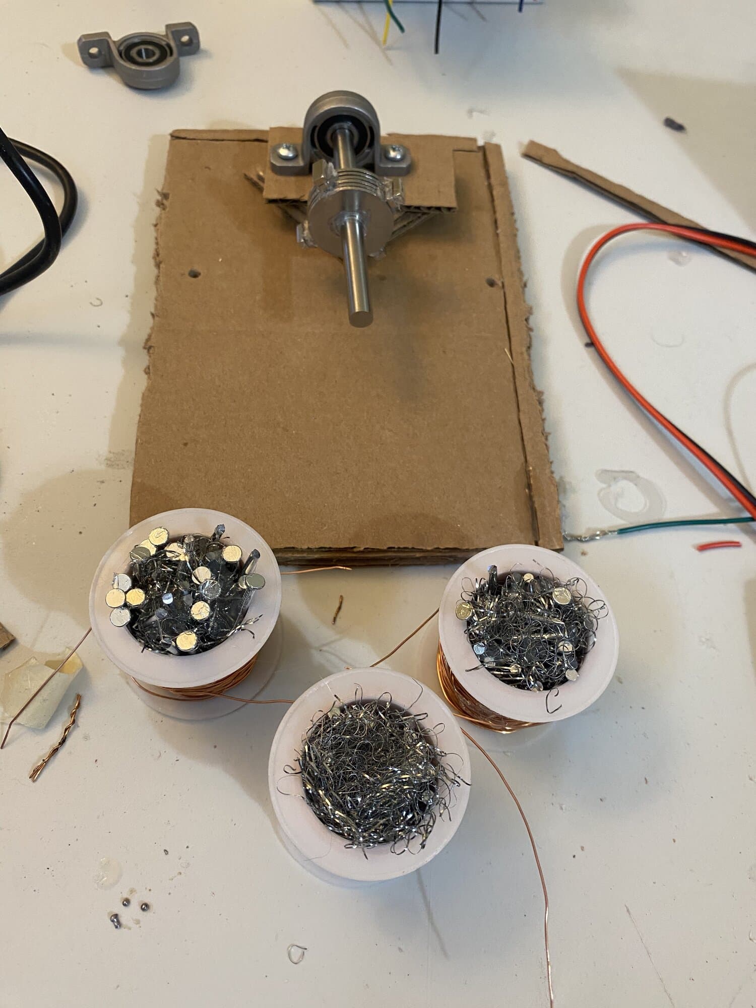
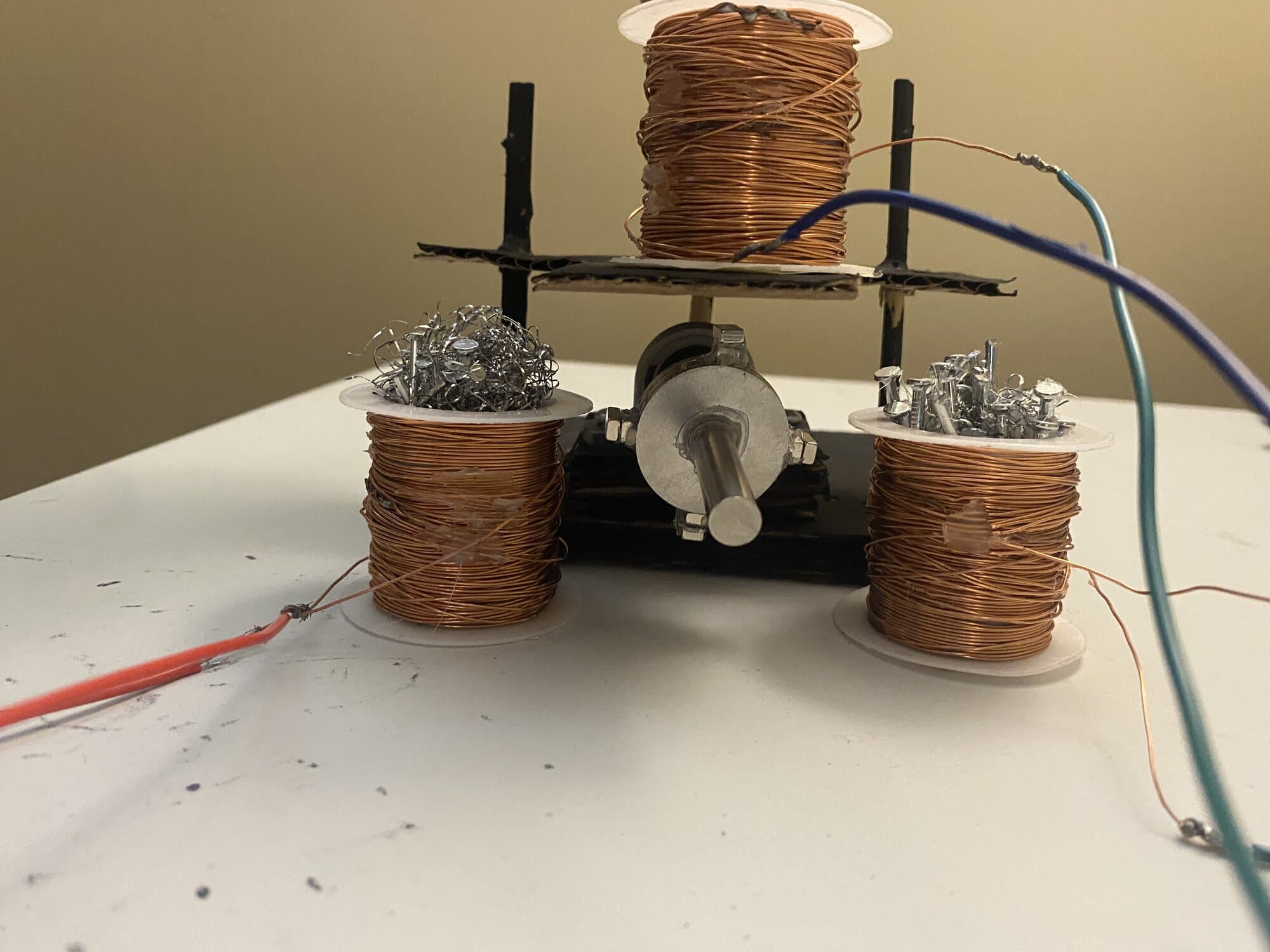
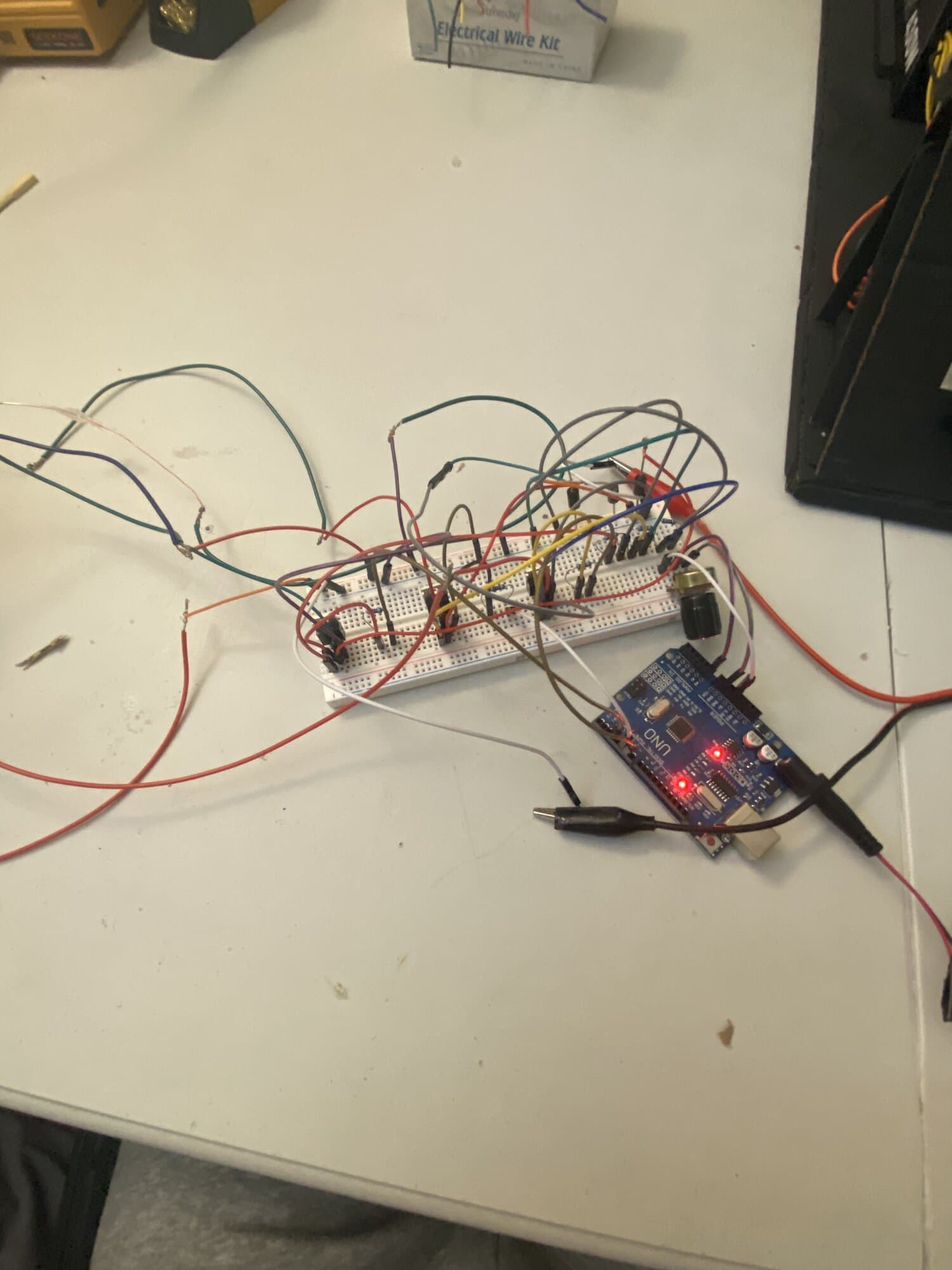
Build Photos
1 / 3
About This Project
Building a 3 phase brushless motor from scratch and creating a PWM controller for it. The goal was to understand how brushless motors work, how they differ from brushed motors, and how a PWM controller works.
Parts & Components
- Arduino Microcontroller
- Serves as the PWM control unit for the brushless motor.
- 3 Empty Spools
- Act as the stator structure used to hold the motor coils in place.
- Enamel Copper Wire
- Used to create the copper coils that generate the electromagnetic field when current passes through them.
- Breadboard
- Used to connect the Arduino and the motor control circuit.
- Power Supply
- Provides external power to the motor circuit.
- Potentiometer
- Used as an adjustable input to control motor speed or power level.
- Magnets
- Used to create the magnetic interaction between the rotor and the energized coils.
- Washers
- Act as the rotor body, holding the magnets and spinning around the stainless steel shaft.
- Stainless Steel Rod
- Acts as the motor shaft, allowing the rotor to spin through the bearing holders.
- 3 Rectifier Diodes
- Help control current flow and protect the circuit from voltage spikes caused by the motor coils.
- IRLZ44N MOSFET
- Works as an electronic switch that allows the Arduino to control higher current going to the motor coils.
- KP08 Bearing Holder
- Supports the stainless steel rod and allows the motor shaft to rotate smoothly.
- Iron Nails / Stainless Steel Wire Brush
- Serves as the iron core inside the copper coils.